
Understanding Accuracy
making practical sense of accuracy specs
If you’re shopping for a scanner, you may be unsure how to interpret the accuracy specifications you find on manufacturers’ brochures & spec sheets. We’ll untangle it here.
Why are there 2 different accuracy specs?
Most manufacturers include a fundamental accuracy spec as well as accuracy over distance. Terminology may vary. Fundamental accuracy may be referred to as “point accuracy” or simply “accuracy.” A typical spec may look something like this:
Accuracy, up to: 0.02 mm (0.0008 inches)
Accuracy Over Distance: 0.015 mm + 0.035 mm/m (0.0006 inches + 0.0004 in/ft)
These results are always plus / minus (±) so the result could be either over or under the true value
Calculating for part size
Since all parts have a size, the accuracy-over-distance spec tends to be the most important. It is a simple formula comprised of 2 values: a base accuracy, followed by the amount lost over a given distance, which may be referred to as the accuracy “stack” value. The second value is added to the first. For example, let’s say our part is 3 meters long and we’ll be scanning it with the Artec Point II.
Based on the spec, this scanner can be expected to lose 0.035 mm over each meter of part size, so we’ll multiply this number by 3 for a result of 0.105 mm.
The we add that result to the initial base accuracy of 0.015 for a final result, which tells us that we can expect an accuracy of ± 0.12 mm on our 3 meter long part.
If that’s all we need to calculate accuracy why is the other accuracy spec included at all?
While the accuracy over distance is usually the only number that matters in the real world, it’s important to understand that the first non-formulaic spec is a fundamental limit that has nothing to do with part size. If we were to apply the Accuracy Over Distance formula to an extremely small or thin part, we could end up getting a very small result, so it’s critical to keep in mind that no result can be better than this fundamental limit regardless of how small the part is.
Accuracy, up to: 0.02 mm (0.0008 inches) « Fundamental Limit
Accuracy Over Distance: 0.015 mm + 0.035 mm/m (0.0006 inches + 0.0004 in/ft)
Resolution ≠ accuracy
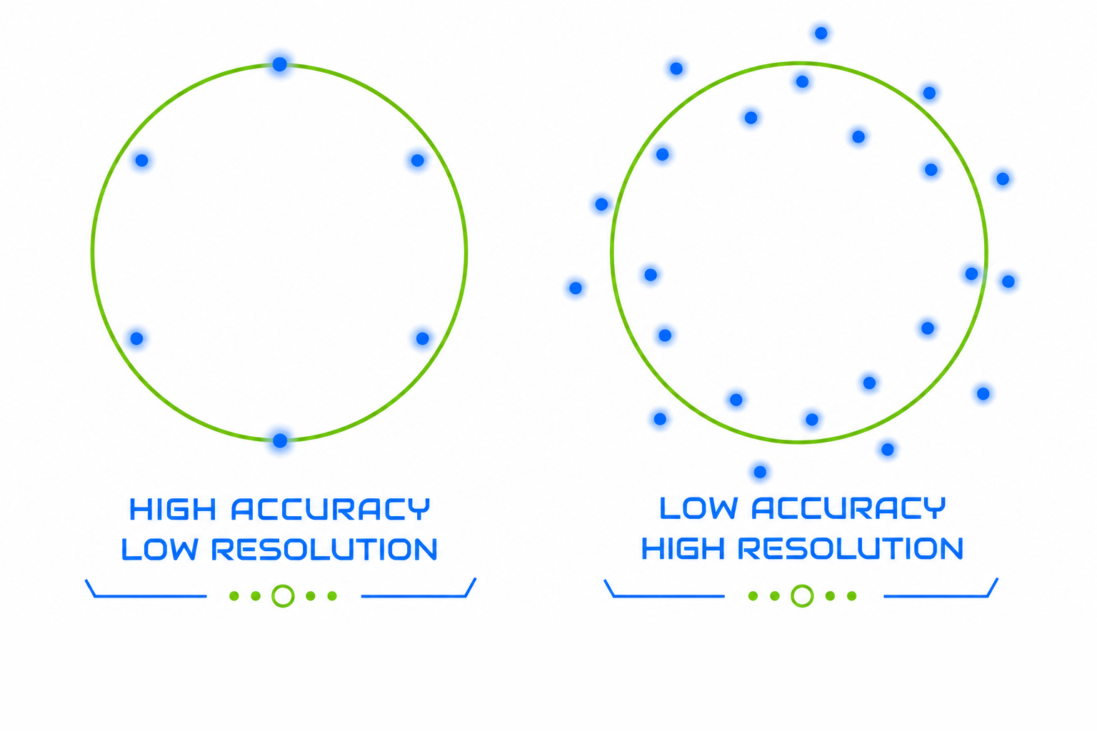
Resolution and dimensional accuracy are not directly related. Resolution refers to the sheer density/number of points, not their proximity to a true value. The locations of captured points can be calculated with great confidence regardless of whether there are many points, or few.
Take this hole location measurement for example. The scan on the left is low resolution with very few points, but they are very close to the actual hole perimeter. The scan on the right is high resolution, but because it is less accurate it confers no benefit in measuring this hole location.
Learn more about Resolution here
A much less common spec is Measurement Resolution, which is different entirely and is indeed related to fundamental accuracy. Measurement Resolution can be related to factors like the wavelengths of various colors of light, the speckle effect of lasers, or the resolution of encoders, but it is generally considered redundant and is far less common to see on sales materials.
The relationship between accuracy & precision
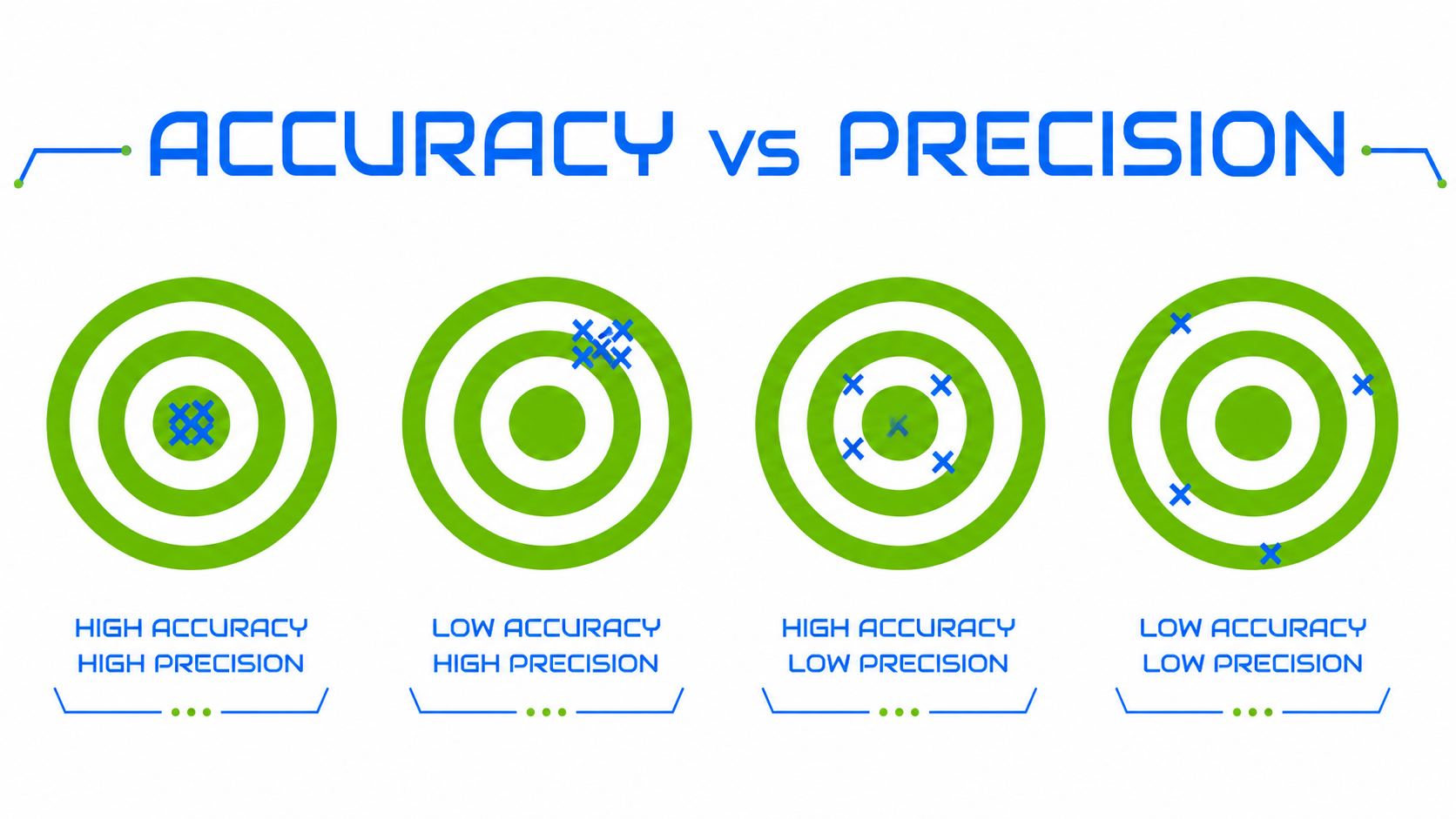
In everyday life, the terms Accuracy and Precision are perfectly interchangeable, but in the 3D scanning world they are more likely to be used within their strict scientific definitions.
Accuracy refers to how close a measurement is to its true value.
Precision on the other hand is a synonym for repeatability - how close multiple measurements are to each other, not to the true value.
It goes without saying that a scanner that severely mismatches these 2 qualities is of limited usefulness, so metrology-grade scanners tend to focus on both of these qualities in equal measure.
Because of the hazy common usage of these terms, some manufacturers avoid the term precision and have opted for the term “repeatability” instead.
ISO, VDI/VDE and other certifications
When dimensional accuracy is critical, the industry relies on certifications and control measures that ensure scanners can be relied on for accuracy and repeatability. Here we’ll summarize the most common standards you’ll encounter while researching 3D scanners.
VDI/VDE
VDI and VDE are German engineering associations that dictate a set of internationally-recognized and highly-rigorous guidelines for metrology and measurement technology. Their standards for calibrating optical devices are popular around the world and are the most widely recognized certifications for structured light scanners.
ISO 17025
ISO’s 17025 standard does not describe a method of calibration, but instead regulates the laboratories that perform such calibrations and ensures their competence to do so. It is an internationally-recognized standard issued by ISO and IEC jointly and controls everything from highly specific management practices to facility requirements such as vibration mitigation and temperature control.
NIST
NIST — the National Institute of Standards and Technology — is an American institute that dictates national standards for traceability. For instance, when a lab certifies its reference spheres or calibration artifacts for a VDI/VDE acceptance test, those artifacts must trace back to a national standard, and in the United States, that standard is governed by NIST.
ISO 12836
ISO standard 12836 ( applies to the Artec Micro II) is an accuracy standard, but one that is specific to the Dental Industry. It ensures the accuracy and repeatability of devices used in the creation of various dental reconstructions such as crowns and bridges.
ISO 10360
ISO’s 10360 standard covers CMMs (coordinate measuring machines) and portable probing arms. It also covers laser scanners attached to such devices. It is a family of standards that apply to certain measurement devices that employ mechanical methods of tracking space and distance, such as gantries, and linear & rotary encoders.
ISO 17123-9
ISO 17123-9 is a sub-section that applies to terrestrial (usually tripod-mounted) LiDAR scanners. It defines procedures for evaluating the repeatability LiDAR scanners that are commonly used in surveying, building, and civil-engineering work.