
what is GD&T?
GD&T stands for Geometric Dimensioning and Tolerancing — a standardized symbolic language, governed in the US by ASME Y14.5, for specifying and controlling the allowable variation in a part’s form, size, orientation, and location relative to its intended design.
Rather than just giving a flat +/- tolerance on a linear dimension, GD&T lets an engineer define exactly what matters about a feature’s geometry — how straight a surface needs to be, how perpendicular a hole is to a face, or how precisely a bolt pattern has to be positioned relative to a reference each. These control factors are defined within a feature control frame on the drawing along with a tolerance value and, where needed, a reference datum.
What are Datums?
A datum is a theoretically exact reference feature (such as a plane, axis, or point) established from a real feature on the physical part. Datums can be the zero point that a drawing is built around, or a feature that other dimensions and tolerances get measured from.
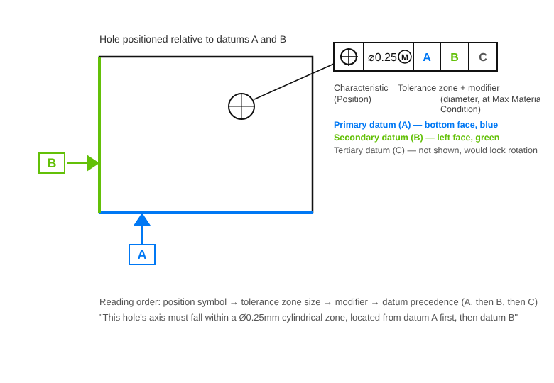
In practice, a datum is called out on the drawing by picking a real feature (a flat face, a bore, a set of mounting holes) and labeling it with a letter in a boxed datum symbol — A, B, C, and so on. When a feature control frame says something needs to be perpendicular or positioned relative to Datum A, that means: take the real, physical surface labeled A on the actual part, treat it as a perfect reference plane, and measure the callout from that.
Most parts use a datum reference frame built from three datums (primary, secondary, tertiary — usually in that A,B,C order), which together lock down all six degrees of freedom, the same way a physical fixture would hold a part in a specific, repeatable orientation on an inspection table. The order matters: the primary datum constrains the most degrees of freedom (usually the surface the part sits flat on), the secondary locks additional ones, and the tertiary resolves what’s left (typically rotation).
GD&T Symbols Reference Chart
The 14 geometric characteristic symbols defined in ASME Y14.5
Form
Every point along a line element or axis must lie within a tolerance zone bounded by two parallel lines (or a cylinder, for an axis).
No DatumEvery point on a surface must lie within a tolerance zone bounded by two parallel planes.
No DatumEvery point on a single circular cross-section must lie within a tolerance zone bounded by two concentric circles.
No DatumThe entire cylindrical surface must lie within a tolerance zone of two coaxial cylinders — it combines roundness, straightness, and taper into one control.
No DatumProfile
Controls a 2D cross-sectional outline of a surface against its theoretically exact profile, evaluated one section at a time.
Datum OptionalControls the full 3D form of a surface against its theoretically exact profile, across the entire surface rather than one section.
Datum OptionalOrientation
Holds a surface, axis, or line exactly 90° to a referenced datum.
Datum RequiredHolds a surface, axis, or line at a specified angle (other than 0° or 90°) to a referenced datum.
Datum RequiredHolds a surface, axis, or line equidistant from a referenced datum at every point.
Datum RequiredLocation
Controls the exact location of a feature of size relative to one or more datums — the most widely used location control.
Datum RequiredRequires the median points of a feature to fall within a cylindrical zone centered on a datum axis. Rarely called out since 2018 — Position is now preferred.
Datum RequiredRequires the median points of a feature to be symmetrically arranged about a datum plane or axis. Also rarely called out since 2018, in favor of Position.
Datum RequiredRunout
Controls form and position variation in a single circular cross-section as the part rotates one full turn about a datum axis.
Datum RequiredControls the entire surface simultaneously across full rotation about a datum axis — combines form, orientation, and location into one check.
Datum RequiredReference only — always verify against the governing drawing and the current ASME Y14.5 standard. © Lightform Solutions LLC